Installing SMA’s Rapid Shutdown System: Tech Tip Video
Check out our latest Tech Tip to learn how to properly install SMA’s Rapid Shutdown System.
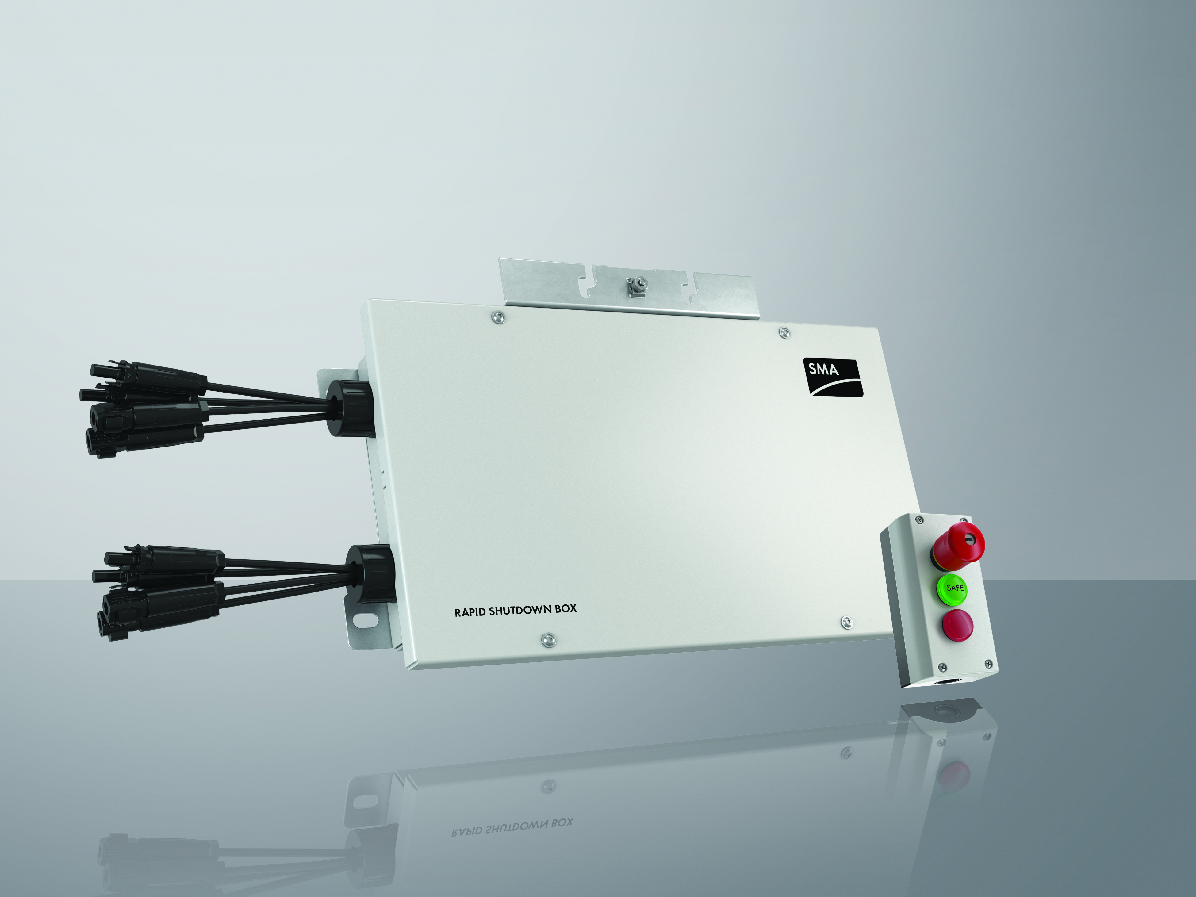
Why choose SMA’s Rapid Shutdown System? First of all, it’s the most cost-effective way to comply with 2014 NEC 690.12 for states that have adopted 2014 NEC or will be adopting it soon. It will also ensure compliance in those states that have adopted 2017 NEC, until the 2019 80-volt limit goes into effect.
Another major reason to select SMA’s Rapid Shutdown System is that it is compatible with our Secure Power Supply functionality for residential string inverters in case of grid outages – whereas other rapid shutdown systems would eliminate such functionality.
Finally, our Rapid Shutdown System is fast to install. It also fits underneath a module, so you won’t need to extend racking to accommodate it.
Watch the video to learn more!


")

If we use this rapid shutdown box, can we also use the Secure Power Supply option? I saw that Secure Power supply does not work with Sunspec rapid shut down, and the Tigo rapid shutdown.
Hello.
Some person told me that SMA is not commercializing this product anymore, is that true? Is there any agent serving Central America? Or United States?
Regards,
Javier Alvarez
HI,
I see the RSB-2S-US-10 is certified with SBx.x-1SP-US-40 under NEC2014, but is it certified for use with SBx.x-1SP-US-41?
Thanks,
I’m interested in this product. Do you have a local agent in Taiwan?
In Alberta, Canada, PV rapid shutdown systems or equipment now must be certified to CSA C22.2 No. 330-17. Does this product have that rating?
The RSD initiator must have C22.2 No. 330. Does the initiator have this rating?
Also inverters must have CSA 22.2 No. 107.1-16, is this the case for the SB3.0-7.7-US-40?
how can I get rapid shutdown box and controller also ups with as well can you let me know please thank you
I am looking for SMA Rapid shut down box and controller can you let me know if you guys have it please thank you
Is it possible to run the control box wire in the same EMT conduit as the DC wires back to the inverter without any interference issues? Should I use shielded cable?
So i have 1 string going in to RSB side A input and one string going in Side B input, both strings have 10 panels. on my out put i have have side A output going to inverter A and B output going to inverter B. have low voltage wire 5 on bottom port with bypass on top port from 3 to 4. my issue is that i cant get power past the RSB, tested all my wire, contacter in Control box and all my feeds. any suggestions? my strings have 350 V going into RSB
I have connected up the arrays and my red light is coming on and not going off, The only thing I can come up with is that we wired the 1-5 pins backwards. Also I have 3650 watts per channel. 1 channel is saying 480 VDC and the other is saying 48
Hello,
Regarding the Rapid Shutdown Box…my company has replaced a bunch on RMA, and it seems one now has failed in the opposite way most others have failed. The ones that we replaced would not turn ON in the morning (no DC power output from the RSB), bad relay or solenoid…
Now it seems there is one that won’t trigger OFF when the RS Controller is engaged (Red Button pushed).
What’s happening inside the RSB? I assume the same relay or solenoid that has previously failed in the OFF position has now failed in the on (continuous voltage to the RSB out) when there is ambient light.
Is this a hazard/must the system be turned off immediately or can we wait for the replacement device? In other words, the relay that turns on at 32 volts in the morning to activate the system is already in the on position (it must be) if the RSB is outputting voltage. Please advise.
Regards,
mark
So can I infer, since they’re not listed, that the RSB is not compatible with older SMA Sunny Boy inverters like the SB 6000US-10?
The system is completely installed, but the green safe light on the rapid shutdown switch isn’t coming on. We checked voltage before and after with a volt meter and the rapid shutdown system is working. It’s just the green light isn’t working. We even flipped the wire feeding red light with the green light wire and the green light turns on but the red didn’t. We checked continuity of the wire and it’s good. We also changed out the connector for the control wire and same issue. So, the green LED works and the device shuts down the system, but green light doesn’t shine. Tells me something is wrong in the SMA rapid shutdown box.
Thoughts?
I am looking at 2 ways of configuring a system please read below.
With 2 out puts on the SMA rapid shut down. 3 in puts on the 5.0-US inverter.
18 panels 300 w 40Volts 9 amps each
Set in 2 strings of 9 panels into the rapid shut down.
Each panel would need to reach 10volts for power production.
Inverter usable input voltage 90v
Rapid shut down into to A and B MPP inputs leaving C not used.
Issue is clipping
How to utilized C MPP for full capacity of the inverter with 2 strings?
To my understanding A, B, C MPP do not go into a common buss.
Another way of doing this is 3 strings of 6 panels
Second rapid shut down box ? for C channel
Inverter usable input voltage 90V.
There for each panel would need to reach 15 volts for power production.
I would appreciate any feed back on the above.
If I am not clear on something please let me know.
I am referencing page 65 in the manual for the 5.0-US inverter.
Thank you
how come the RSB does not have 3 channels to match the 3 mmpts in the inverters?
I have installed multiple rapid boxes and it seems like a hit and miss with them working properly. When I connect more then one rapid box is there a specific way the wiring from the button to the other boxes must be done?
Hi I just wired two Rapid shutdown boxes with the wires from the button to box A, lower pin terminals. Then from box A’s upper 5 terminals, I went to box B’s lower terminals. Then in box B, I jumper the upper 3&4 terminals. Is this correct?
In the manual it seemed to be telling me that box B would have jumper 3&4 in the lower terminals, but I already had the wires from box A there…
I have one rapid shutdwon and your manual is confusing. What awg size jumper do I use between terminal 3 and 4 of the second five-pole plug. It says to use a jumper rated for the maximum system voltage? I have only two strings of 10 and 11 panels. Can the jumper be the same 18 awg as the conductors going into the bottom plug? What is the maximun size AWG that the plug will take. Why does everything have to be so confusing.
Also, on page 23 of the manual, am I to assume that pin 5 is the top pin on the side of the rapid shutdown mounting bracket, as shown?
Hi,
Is the Rapid shutdown system can also be used for commercial scale PV system, 100-1M Wp solar PV rooftop installation using SMA STP60 or SMA STP25000TL
Hello SMA team,
I think installation manual of Rapid Shutdown shows wiring to the controller is wrong (please correct me if I am reading it wrong). On page 25 – fig 9 – It shows red wire (pin no 1) from rapid shutdown box going to (o) – common wires of both LED’s (Red and Green). However it should goes to one side of rapid shutdown on/off switch (+12V_ – X2).
No. 3 wire from Rapid Shutdown Box which is (o) should go to common wire (jumper wire of both LED’s) of both led (red and green).
I am comparing wiring pin diagram on page 23 fig 8 which shows 1-5 connections pins inside rapid shutdown box.
The visual picture is confusing me as if I go pin by then then its not the same – Please correct. Also, why the visual in installation manual is so foggy that its hard to make out?
Thanks!
Uttam
Manual I am reading from
sma.de/dl/27991/RSS-US-IA-xx-14.pdf
The channel B always problem not working only channel A why string has power and inside the rapid shut down has power but not in the output connection for inverter
I have a large 19.8kW residential system being designed. Given the size, most of three roof orientations (south, east & west) will be covered with panels. Finally, we are utilizing three SB70-1SP-US-40 inverters with a total of 9 strings (3 strings per inverter). Each roof orientation has a string going to one of the three inverters. Given the layout I don’t want to have to purchase 9 RSBs and only be able to use one channel per RSB. I am hoping I can purchase 5 RSBs utilizing both A & B channels on 4 of them and just the A channel on the 5th one. However, this will require that I be able to run a string going to Inverter #1 and a string going to Inverter #2 through a single RSB. So here is my question… Are the A & B channels sufficiently independent that I can hook up a string going one inverter and a string going to a different inverter through a single RSB?